Measurements and Features
| Measurements |
5700
|
Elite
|
|---|---|---|
| Temperature (°F | °C) |
●
|
●
|
| Wind Chill (°F | °C) |
●
|
●
|
| Relative Humidity (%) |
●
|
●
|
| Heat Stress Index (°F | °C) |
●
|
●
|
| Dewpoint Temp (°F | °C) |
●
|
●
|
| Wet Bulb Temp (°F | °C) |
●
|
●
|
| Station Pressure (Absolute Pressure) |
●
|
●
|
| Barometric Pressure (inHg | hPA | psi | mb) |
●
|
●
|
| Altitude, m | ft |
●
|
●
|
| Density Altitude, m | ft |
●
|
●
|
| Features |
5700
|
Elite
|
| LiNK Wireless Connectivity + LiNK Ballistics Mobile App |
●
|
●
(optional) |
| Night Vision Preserving Back Light |
●
|
●
|
| Measurements |
5700
|
Elite
|
| G1/G7 Ballistic Solver |
●
|
●
|
| Muzzle Velocity Calibration |
●
|
●
|
| Target Range Estimator |
●
|
●
|
| Muzzle Velocity-Temperature Table |
●
|
●
|
| Spin Drift |
●
|
●
|
| Coriollis Correction |
●
|
●
|
| Aerodynamic Jump Correction |
●
|
●
|
| Gun Memory |
3
|
16
|
| Targets |
1
|
10
|
| Ballistics Data |
Limited
|
Full
|
| AB Custom Drag Models |
●
|
|
| Range Card |
●
|
|
| DSF Calibration |
●
|
|
| Multi Target |
●
|
|
| Easy Mode |
●
|
●
|
Getting to Know Your Kestrel

Buttons
| Button | Name | Function |
|---|---|---|
| POWER | Turns Kestrel on and off. Press for on, hold for two seconds to turn off. | |
| OPTIONS/ EXIT | Enter the main Options menu or exit a menu. | |
| SELECT | Access Settings on any measurement screen or select a menu option to enter its submenu or confirm a task. | |
| UP/DOWN | Scroll up and down through measurement screens or menus. Adjust values when entering text in name menus. | |
| LEFT/RIGHT | Scroll options left and right. Adjust values in combo menus and setting submenus. | |
| CAPTURE | In Weather Mode, manually capture all environmental values. In Ballistics mode, turns on and off continuous wind capture. | |
| BACKLIGHT | Turn backlight on or off. (Also turns off automatically after one minute.) |
Kestrel Options Menu
Most system-wide and weather setup options are accessed from the main Options menu by pressing the ![]() button from any Weather Measurement Screen or the main Targeting Screen.
button from any Weather Measurement Screen or the main Targeting Screen.
- MODE
- BLUETOOTH
- Bluetooth On/Off
- Conct
- DATA PORT
- MEMORY OPTIONS
- Clear Log
- Auto Store
- Store Rate
- Overwrite
- GRAPH SCALE
- DISPLAY
- Auto Shutdown
- Contrast
- Backlight
- SYSTEM
- Time & Date
- Compass Cal
- Measurements
- Units
- Lang
- Batt
- Humidity Cal
- Factory Restore
- ABOUT
- Version
- Legal
Kestrel Operating Mode
Your Kestrel Ballistics Weather Meter is both a complete weather meter AND an advanced ballistics calculator. You must select either Weather Mode, Ballistics Mode or Easy Mode depending on the functions you desire:
- Weather Measurements, History and Data Logs are accessed in Weather Mode.
- The Targeting Screen and all ballistics settings (Target, Wind, Gun, Environment, Range Card, Ballistics, Manage Guns) are accessed in Ballistics Mode.
- Easy Mode is a simplified version of Ballistics mode with additional guidance for users new to using the Kestrel.
NOTE! You can also "jump" between Weather and Ballistic modes by pressing the ![]() BACKLIGHT button twice quickly. You will enter Weather Mode at the last Measurement Screen used, making it convenient to take advanced wind averaging measurements, for example.
BACKLIGHT button twice quickly. You will enter Weather Mode at the last Measurement Screen used, making it convenient to take advanced wind averaging measurements, for example.
Kestrel Menu Navigation
Types of Menu Items

Targeting Screen

Weather Mode Screen
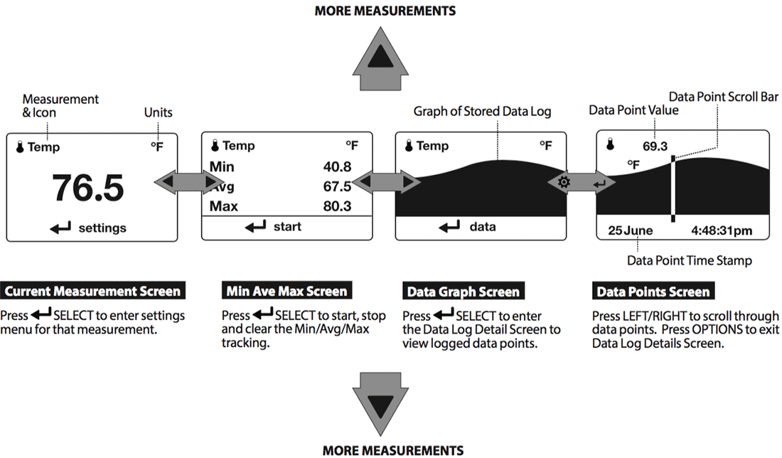
- The
 UP/DOWN buttons navigate between all weather measurements set to "On" in Options|Measurements.
 - The
 LEFT/RIGHT buttons scroll between the three display screens for the measurement.
 - The
 OPTIONS button exits the settings submenu and Data Log Detail Screen.
Getting Started
- INSTALL BATTERY. Slide the battery door latch and open door. Insert the provided AA lithium battery as indicated by the label. Replace the battery door, ensuring it "clicks"" fully into place.
-
POWER ON KESTREL. Press
 to power on Kestrel.
 -
ENTER OPTIONS MENU. Press to enter the Options Menu.
-
CALIBRATE THE COMPASS. Scroll to and select System. Scroll to and select Compass Cal. Follow the on-screen instructions:
- Place the base of the Kestrel on a flat surface at least 3 feet from any large metal objects.
- Start the calibration routine. Rotate the Kestrel around its vertical axis 3 times, keeping the unit as vertical as possible and taking approximately 10 seconds per full rotation. You may need to restart the routine a few times until you get the timing correct.
Note! When taking compass readings, keep the Kestrel as vertical as possible for maximum accuracy.
- EXIT OPTIONS MENU.


Additional Settings
All additional settings are accessed from the options menu.
- SET AUTO SHUTDOWN. Scroll to and select Display. Scroll to Auto Shtdwn and choose a time window after which the Kestrel will shut down without any button presses.
- SET BACK LIGHT. Scroll to and select Display. Scroll to Backlight and set to either standard White or night vision preserving Red.
- SET DATE AND TIME. Scroll to and select System. Scroll to and select Time & Date. Adjust the time and date.
- TURN ON/OFF MEASUREMENT SCREENS.Scroll to and select System. Scroll to and select Measurements. Set each measurement screen to either On or Off as desired.
- SET UNITS. Scroll to and select System. Scroll to and select Units. To change all units select Global, then set Global to Imperial or Metric, and then scroll to Apply and select Go. To set units individually, scroll to each measurement type in the Units submenu and set to the desired units. Units can also be set in the Settings menu for each measurement.
Altimeter and Barometer
The Kestrel employs a stable, accurate pressure sensor to measure station pressure, the unadjusted air pressure in your location.
- To use your Kestrel to measure barometric pressure (station pressure adjusted for local elevation), you must enter a correct reference value for your altitude. Accurate barometric readings require that no elevation changes be made while taking measurements.
- To use your Kestrel to measure altitude changes (changes in station pressure associated with changes in elevation), you must enter a correct reference value for your starting barometric pressure. Accurate altitude readings depend on stable, weather related barometric air pressure while measurements are taken.
- Synched values between the Altitude and Barometer measurement screens allow reference value updates on either screen to automatically update reference values on the other. You cannot use your Kestrel as a barometer and altimeter simultaneously.
Setting reference values on Baro measurement screen:
- Scroll to the Baro measurement screen and select Settings.
- Adjust either the Altitude or the Barometric Pressure value to a local, known value obtained from a mapping reference, GPS, or accurate weather station in the same location.
Setting reference values on altitude measurement screen:
- Scroll to the ALTITUDE measurement screen and select Settings.
- Adjust either the Altitude or the Barometric Pressure value to a local, known value obtained from a mapping reference, GPS, or accurate weather station in the same location.
Note! You should enter new reference values whenever you are using the Altimeter or Barometer functions and your location or the weather conditions have changed.
Note! You do NOT need to enter Altimeter or Barometer reference values to obtain accurate ballistics targeting solutions. The ballistics calculator employs the station pressure.
Creating Gun & Bullet Profiles
Note! Unless specified, all ballistics related functions are to be accessed with the Kestrel in Ballistics Mode. Features found in Easy Mode are called out specifically.
For ease of access, the ballistics Targeting Screen also contains the Ballistics Menu. Simply scroll down from the Targeting Screen to access these settings and submenus:
- Target
- Wind
- Gun
- Environment
- Range Card (Elite Model only)
- Multi Target (Elite Model only)
- Ballistics (Limited on 5700 model, full on Elite model)
- Manage Guns
Note! The back of this guide contains a full Glossary of the terms used. Please read these definitions!
CREATE OR EDIT A GUN PROFILE:
- Scroll to and select Manage Guns. Either select an existing gun to edit or select New Gun.
- Scroll up and select Gun to rename the gun. Use the scroll/adjust buttons to enter a new name, then exit the naming menu.
- Set the remaining values in the Gun sub menu to match your gun, bullet and scope combination.
- Exit to the Manage Guns menu and ensure the new gun is set to On.
Creating Targets
Edit Target
- Scroll to and select Tgt.
- Set range, angle, target speed, and wind values to match your target.
Edit Target or Create Additional Targets (Elite model only)
- Scroll to and select Tgt.
- Set range, angle, target speed, and wind values to match your target.
The Elite model allows up to ten targets (A TO J). - Make sure Target is set to Active.
- To enable more than one target, or edit other active targets, scroll up to the header named Target and use the left/right buttons to scroll between targets (A through J). Set a target to Active to enable it, then edit its values.
- When only one target is active, its range can also be modified directly from the main Targeting Screen by highlighting Tgt and scrolling left or right.
- If more than one target is set to Active, highlighting Tgt in the main Targeting screen and scrolling left or right will scroll between active targets.
Measuring Wind
An accurate crosswind measurement requires that the Kestrel “know” both the direction of fire and the wind direction and strength. You may use the Kestrel’s built-in compass and wind measuring and averaging features to capture these values:
Capturing the Direction of Fire:
- Select Tgt to enter the Target menu, scroll down and select DoF, then scroll down and select Capture.
- Follow the on-screen instructions:
- While holding the Kestrel vertical, point the back of the unit directly towards the target and select Capture.
- DoF will automatically be populated in the Target menu.
Capturing the Wind Inputs:
- In the Target menu, scroll down and select WD, WS1, or WS2.
- Scroll down and select Capture.
- Follow the on-screen instructions:
- While holding the Kestrel vertical, point the back of the unit directly into the wind and select Capture.
- Continue to point the Kestrel into the wind for at least 5 seconds to capture a rolling 5 second average and peak value of the winds. Select End Capture.
- WD, WS1, WS2 will automatically be populated in the Target menu.
Note! Selecting Wind in the Ballistics Menu jumps directly to the WD, WS1, WS2 entries in the Target Menu.
Note! For maximum accuracy of compass readings when capturing DoF and Wind, the Kestrel must be held as vertically as possible – be careful not to tilt it away from you while taking readings.
Note! Any time you are using the Kestrel to calculate an elevation hold (including when calibrating muzzle velocity and DSF) a direction of fire plus wind direction and speeds must be input. These inputs contribute to an accurate elevation solution.
Calibrating Muzzle Velocity
The Muzzle Velocity Calibration function allows you to obtain a more accurate muzzle velocity by combining user input data and actual shot results and calculating the actual bullet speed.
Calibrating Muzzle Velocity
- Scroll to and select Gun in the Ballistics Menu.
- After accurately inputting all other gun, bullet, and scope parameters, as well as wind values and direction of fire, scroll to MV and adjust to your best estimate of your gun’s muzzle velocity.
- Select MV to enter the MV sub menu. Scroll to and select Cal MV.
- The Cal MV range is the suggested target distance at which to calibrate. For best results, find a range where you can shoot to between 85% and 100% of the recommended range but no further. Calibrating at less than 85% of the recommended range will lessen accuracy at distances near the transonic boundary. If a target beyond 85% of the recommended range is not available, calibrating at a shorter distance should be accurate out to the distance used for calibration but a new MV Calibration should be performed if shooting beyond the calibration distance.
- Adjust Range to match the actual distance to your target where you are shooting. Accuracy here is key! Use a quality ranger finder or confirm your range using the best method available.
- Apply the suggested elevation hold shown in Drop in your scope turrets or reticle.
- Take a number of shots to determine the actual bullet drop. Adjust Drop to match the actual observed bullet drop of the bullet at that range. For example, if the point of impact is 1.5 Mils below the bullseye adjust the Drop value to be 1.5 Mils greater.
- A new MV will be calculated to match the actual impact of your round. (In this example, the MV will be decreased.) No chronograph required!
- A (+) or (-) in front of the MV value indicates the new MV has been calibrated up or down.
- Exit to accept the new MV value.
Note! The suggested MV Cal range is the distance where the bullet slows to Mach 1.2. If the suggested range cannot be matched it is better to shoot at a shorter/closer distance rather than further. However, as the MV calibration range decreases, so does MV calibration accuracy. Try to shoot as close to the recommended MV Cal range as possible.
Note! If the MV-Temp table has been populated, MV values will be locked by the MV-Temp table and MV values will not be automatically adjusted by the MV Cal procedure above.
Using Cal MV Guide
In the MV sub menu, below Cal MV, is the Cal MV Guide tool. This tool provides the user with step by step guidance through the MV Calibration process to ensure muzzle velocity is calibrated as accurately as possible. If used correctly, both the Cal MV and Cal MV Guide tool should produce the same result.
Calibrating Drop Scale Factor (Elite Models Only)
The Drop Scale Factor (DSF) function allows you to calibrate the BC of your round beyond the supersonic range of the bullet and maintain accurate solutions out to transonic and subsonic ranges. DSF calibration does not impact the supersonic flight path of the bullet.
Calibrating DSF
- Scroll to and select Gun in the Ballistics Menu.
- After accurately inputting all other gun, bullet, and scope parameters, as well as MV, wind values and direction of fire, scroll to and select CAL DSF.
- The Cal DSF range is the suggested target distance at which to calibrate beyond. (Not closer than, as with MV Calibration). The suggested range shown when performing a Cal DSF for the first time corresponds with a bullet velocity of Mach 0.9. Subsequent uses of Cal DSF will provide a suggested ranges corresponding to a Mach value which is slower than the Mach value used in the previous DSF Calibration.
- Adjust Range to match the actual distance to your target where you are shooting. Accuracy here is key! Use a quality ranger finder or confirm your range using the best method available.
- Apply the suggested elevation hold shown in Drop in your scope turrets or reticle.
- Take a number of shots to determine the actual bullet drop. Adjust Drop to match the actual observed bullet drop of the bullet at that range. For example, if the point of impact is 1.5 Mils below the bullseye, adjust the Drop value to be 1.5 Mils greater.
- A new DSF value will be calculated to match the actual impact of your round in the transonic or subsonic range.
- A (+) or (-) in front of the DSF value indicates the DSF value has been calibrated up or down. A DSF value of 1 indicates no change to BC in the transonic or subsonic range.
- Exit to accept the new DSF value.
- Up to 6 DSF values can be created to calibrate BC through the transonic and subsonic range. Calibrating DSF one time can create more than one DSF Cal value.
- All DSF values can be viewed and deleted in View DSF.
Note! Entering DSF values at a shorter range than any previously entered DSF values will overwrite the longer range values.
Environment
Accurate Temperature, Humidity and Pressure measurements are critical to calculating an accurate Targeting Solution. It is important that the values measured by the Kestrel represent the ambient values, and for this the Kestrel needs continuous airflow over its sensors. When using a Kestrel in a position where airflow could be restricted, such as low to the ground or resting on a shooting mat or rock, it is better to make periodic environmental captures to avoid inaccurate measurements.
How to Capture Environmental measurements
- In the Ballistics Menu, scroll to Enviro.
- Adjust Enviro to Live and then wave the Kestrel rapidly through the air for 5-10 seconds. Next check the temperature shown and wave the Kestrel again. Repeat until the temperature value stops changing. If the area allows, and your lanyard is secure, you may also spin the Kestrel around by the lanyard to increase airflow over the sensors and measure ambient temperature as fast as possible.
- Once the temperature value stops changing, immediately adjust Enviro back to Lock to fix the environmental measurements you have just captured.
NOTE! Repeat this process every half hour or any time the temperature or pressure changes significantly.
How to Set the Latitude
Latitude is necessary for accurate Coriolis calculations.
- In the Ballistics Menu, scroll to and select Enviro then scroll to Lat.
- Adjust Lat to match your local latitude.
NOTE! Latitude default is the middle of North America if no new value is entered. Setting both DoF and Lat to 0 will effectively turn Coriolis correction off.
Continuous Wind Capture
As an alternative to the Wind Capture method described previously, you may mount your Kestrel on a tripod using the Kestrel Vane Mount. The Vane Mount ensures the Kestrel remains oriented into the wind and allows for continuous update of the windage solution. For convenience, this method works best when the firing solution is being displayed on a mobile device using Kestrel LiNK Ballistics.
How to Set the Kestrel to Continuous Wind Capture
- Select the correct Gun and Target and set the Direction of Fire.
- In the Ballistics Menu, highlight Wind and press the red Capture button. An arrow will appear next to the Wind menu item to indicate the unit is now in wind capture mode.
- While in wind capture mode, manual inputs to the unit will be locked and changes in wind speed or direction will automatically update the Targeting Screen Windage solution.
- To close wind capture press the red Capture button again.
Multi Target (Elite Models Only)
Kestrel Elite units hold target data such as range direction of fire, inclination angle and wind values for 10 separate targets. Multi Target is a tool for inputting target data and then viewing solutions for all 10 targets quickly.
How to Use Multi Target
- In the main ballistics menu, scroll to Multi Target and press Select.
- Scroll up or down to view the 10 different target solutions. Scrolling left or right will change the solution data shown.
- To input target data, enter the Multi Target sub menu by pressing Select while the Multi Target screen is showing.
- To input target range, direction of fire (DoF) or inclination angle (Ideg), highlight Target Inputs and press select.
- The first option is to capture one direction of fire and apply it to all targets. This is used if all targets are in roughly the same direction and exact accuracy is not essential. After pressing select, follow the on screen instructions and point the back of the unit at the targets and then press Select to capture the DoF value shown.
- If a unique DoF is desired for each target, scroll down to the target and press the capture button twice to capture the DoF for that target.
- Target range can be input by highlighting the desired target and scrolling left or right till the correct target range is shown.
- Ideg and target speed can be input by highlighting the desired target and pressing select to enter that target’s submenu where Ideg and TS values can be input.
- If using a LiNK connected range finder, simply highlight the desired target and range the target to input any values the range finder can measure.
- To input wind information highlight Wind Inputs and press select.
- The first option is to capture values for WD, WS1 and WS2 and apply them to all targets. This is used if the wind profile for all targets is roughly similar. After pressing select, hold the back of the Kestrel into the wind and after measuring at least 5 seconds of representative wind, press select to end the capture.
- Next you may edit any of the wind values captured, In case you want to alter wind values according to what you can see down range, or accept them by pressing select to continue. These values will then be applied to all 10 targets. While capturing, the wind direction value shown will be in relation to target A (or 1). Once Continue is pressed, the wind direction will be applied to each target in relation to that target’s direction of fire.
- If a unique wind profile is desired for each target, scroll down to the desired target and press the capture button to start a wind capture. After measuring at least 5 seconds of representative wind, press he capture button again to end the capture.
- The target designator (either ABC or 123) can be changed in the Multi Target sub menu by scrolling to Designator and toggling right or left.
- To clear target data for all 10 targets, scroll to Clear All Tgts in the Multi target sub menu and press Select and then confirm your choice. This will reset Target Range to the selected gun’s zero range, DoF to 12:00 and Ideg, TS, WD, WS1 and WS2 to zero.
Connecting to Devices Using LiNK
If your Kestrel is marked LiNK on the bottom front label, it can be connected wirelessly to other LiNK-compatible devices. LiNK is powered by Bluetooth Smart®, also known as Bluetooth® LE, which is available in most iOS devices released after 2014 and Android devices released after 2015, as well as in a USB Dongle available from Kestrel that supports connectivity to Windows and Mac OS devices. LiNK-enabled Kestrel units can connect to mobile devices running Kestrel LiNK Ballistics allowing you to view your targeting solutions remotely, build and manage gun profiles, access the Applied Ballistics custom drag models and install firmware updates. LiNK-enabled units can be connected wirelessly to computers using the Kestrel Dongle. On Windows PC’s use the Applied Ballistics Profile Loader to create and install gun profiles and access the Applied Ballistics custom drag model library. (Applied Ballistics custom drag models can only be used in Elite model Kestrel meters.)
Using Privacy PIN Mode
- To prevent unauthorized apps from connecting to your Kestrel, enter the Bluetooth menu and set Conct to PC/Mobile, then turn Privacy PIN to On.
- When connecting for the first consecutive time to a Privacy PIN compatible app, copy the PIN from the Kestrel’s Bluetooth menu screen to the app.
- If Privacy PIN is set to ON, any apps or computer programs which connect without being able to provide the correct Privacy PIN number will be disconnected.
Connecting to a Computer, Mobile Phone, or Tablet
- On your phone or tablet, follow the links at to locate Kestrel LiNK Ballistics for iOS or Android in the App or Play store and install on your mobile device.
OR - On your computer, follow the links at to locate the Applied Ballistics Profile Loader for Windows or MacOS and install on your computer. Insert your Kestrel USB Dongle (available separately) into an open USB port.
- On the Kestrel, open the Options Menu and select Bluetooth. Set Bluetooth to On. Set Conct to PC/Mobile mode, the Kestrel's Status will change to Available, indicating that it is available for pairing with a computer or mobile device.
- Ensure the computer or mobile device is searching and in range. When Status changes from Available to Connected, the pairing is active and your Kestrel is ready to communicate.
Connecting to a New LiNK-Compatible Device: (Such as a Range Finder)
- Follow directions for your LiNK-compatible Device to power it on and put it in pairing mode.
- On the Kestrel, open the Options Menu and select Bluetooth. Set Bluetooth to On.
- Set Conct to Device.
- Scroll to Name and select New, then wait for the list of available devices in range to populate.
- Select a device from the available list. Once connected, the settings menu for that device will open, allowing you to manage the device's settings.
- Exit to the Bluetooth menu. Status should indicate Connected, meaning the pairing is active and your Kestrel is ready to communicate.
Pairing to a Previously Paired Device
- Follow the directions for connecting to a new device except instead of selecting New in the Name field, scroll left or right to find the desired device.
- Status will change to Searching. If the device is in range and in active pairing mode, a connection will be made and Searching will change to Connected, indicating that the pairing is active and your Kestrel is ready to communicate.
Bluetooth Connection Indicator
- When connected to any LiNK compatible device, a
 icon will appear in the Targeting screen in the upper right.
 - If the paired device goes to sleep or if the connection is lost, the icon may disappear but waking the device up or returning within range should automatically reestablish the connection and the icon should reappear.
Note! LiNK range is typically 100 ft/30M line of sight. Shorter distances should be expected if there are obstacles such as walls or metal enclosures. Range is also impacted by the signal strength of the other device.
Connecting to Computers Using USB Cable
All Kestrel 5 Series units can connect to a computer via the Data Transfer Port using the USB Data Transfer Cable available separately. Kestrel LiNK software is available for Windows and Mac for downloading logged weather data and installing firmware updates. Applied Ballistics Profile Loader is available for Windows only and can be used to create and install gun profiles and access the Applied Ballistics Custom Drag Model Library. (Applied Ballistics Custom Drag Models can only be used in Elite units.)
Connect Your Kestrel Meter to your Computer Using the Data Transfer Cable
- On your computer, follow the links at to download Kestrel LiNK for PC or Mac. Install.
OR (Windows only) - Follow the links at to download the Applied Ballistics Profile Loader to a PC. Install.
- On your Kestrel in the main Options menu, scroll to and select Data Port and set to On.
- Insert the USB Data Transfer Cable into a USB port and plug into the Data Transfer Port on the back of the Kestrel unit.
- Follow the directions in the Kestrel LiNK or Applied Ballistics Profile Loader program to confirm the connection and perform program actions.
Weather Glossary
DIRECTION - Compass heading in true or magnetic North.
WIND SPD - Wind Speed is the measurement of the wind passing through the impeller. For greatest accuracy, point the back of the Kestrel directly into the wind.
CROSWND - Crosswind uses the internal compass and a user selected heading to calculate the crosswind component of the full wind.
HEADWND - Headwind uses the internal compass and a user selected heading or target direction to calculate the headwind component of the full wind.
TEMP - Ambient Temperature is the temperature measured at the thermistor. For best results, ensure the thermistor is not exposed to direct sunlight and is exposed to good airflow.
CHILL - Wind Chill is a calculated value of the perceived temperature based on temperature and wind speed.
HUMIDITY - Relative Humidity is the amount of moisture currently held by the air as a percentage of the total possible moisture that the air could hold.
HEAT INDEX - Heat Index is a calculated value of the perceived temperature based on temperature and relative humidity.
DEW POINT - Dew Point is the temperature at which water vapor will begin to condense out of the air.
WET BULB - Wet Bulb is the lowest temperature that can be reached in the existing environment by cooling through evaporation. Wet Bulb is always equal to or lower than ambient temperature.
BARO - Barometric Pressure is the local station (or absolute) pressure adjusted to mean pressure. An accurate reading depends on a correct altitude input and unchanging altitude while measuring.
ALTITUDE - Altitude is the vertical distance associated with given atmospheric pressure. An accurate reading depends on correct initial barometric pressure input and stable barometric pressure while measuring.
STATION - Station Pressure (Absolute Pressure) is the pressure exerted by the atmosphere at the location.
DENS ALT - Density Altitude is the altitude at which the density of the theoretical standard atmospheric conditions (ISA) would match the actual local air density.
Impeller Replacement
Note! Press only the sides of the impeller when removing and inserting to avoid damaging the precision hub bearing. [Figure 1]
- Press FIRMLY on the impeller module to remove it.
- Insert the new impeller so the side that has the small triangle (close to the perimeter) faces the front of the Kestrel when installed.
- Orient one "arm"" of the module straight up. [Figure 2]. The impeller can be pushed in from either side.

